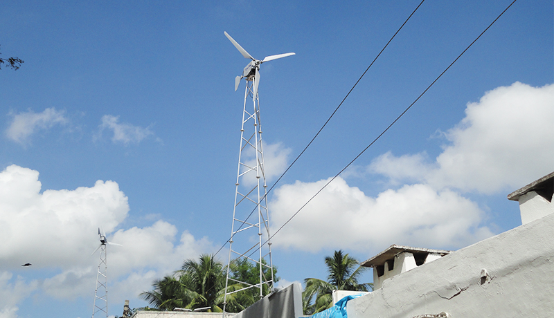
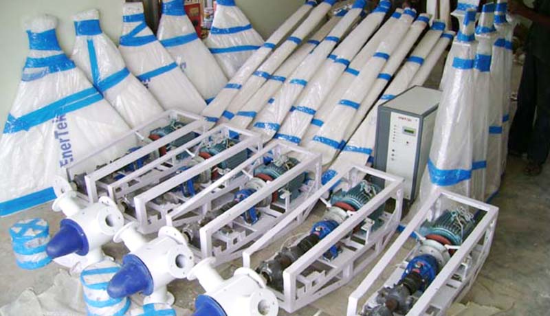
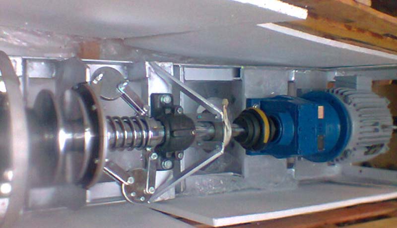
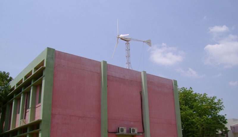
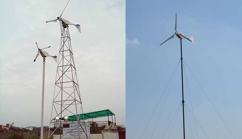
Vaigunth specializes in providing the most economical power solution be it, using free energy from wind, passive solar, solar panels, or any combination they’re of. We have personally tested all of our components to ensure our systems are assembled with the most compatible, quality, robust, commercially available components on the market, our wind turbines are designed for low rated velocity (Less than 9.5 m/s).
Technical Specification
| AR-500W | AR-200W | AR-1KW | AR-2KW | AR-5KW | AR-7.5KW | AR-20KW | AR-30KW | |
| Type | Battery Charger | Battery Charger | Battery Charger | Battery Charger | Battery Charger or Grid Tied | Battery Charger or Grid Tied | Battery Charging or Grid Tied | Battery Charging or Grid Tied |
| PERFORMANCE PARAMETERS: | ||||||||
| Rated Electrical Power | 500 W @ 9.5 m/s | 200 W @ 9.2 m/s | 1000 W @ 9.7 m/s | 2000 W @ 9.5 m/s | 5000 W @ 9.5 m/s | 7500 W @ 9.7 m/s | 20000 W @ 10.5 m/s | 30000W @ 10.7m/s |
| Rated Wind Speed | 9.5 m/s | 9.2 m/s | 9.7 m/s | 9.5 m/s | 9.5 m/s | 9.7 m/s | 10.5 m/s | 10.5 m/s |
| cut-in | 3.0 m/s | 3.5 m/s | 3.5 m/s | 3.5 m/s | 3.5 m/s | 3.5 m/s | 3.5 m/s | 3.5 m/s |
| shut-down (high wind) | 23 m/s | 23 m/s | 23 m/s | 23 m/s | 23 m/s | 23 m/s | 23 m/s | 23 m/s |
| peak (survival) | 60 m/s | 60 m/s | 60 m/s | 60 m/s | 60 m/s | 60 m/s | 50 m/s | 50 m/s |
| ROTOR | ||||||||
| Type of Hub | Fixed Pitch | Fixed Pitch | Fixed Pitch | Fixed Pitch | Fixed Pitch | Fixed Pitch | Fixed Pitch | Fixed Pitch |
| Rotor Diameter | 2 m | 1.5 m | 3.2 m | 4.5 m | 6.8 m | 7.5 m | 10.5 m | 13.9 m |
| Swept Area | 3.14 m2 | 1.766 m2 | 8.03 m2 | 15.8 m2 | 36.3 m2 | 44.2 m2 | 86.54 m2 | 151.5 m2 |
| Number of Blades | 3 | 3 | 3 | 3 | 3 | 3 | 3 | 3 |
| Rotor Speed @ rated wind speed | 500 RPM | 500 RPM | 340 RPM | 250 RPM | 167 RPM | 150 RPM | 140 RPM | 88 RPM |
| Location Relative to Tower | Up Wind | Up Wind | Up Wind | Up Wind | Up Wind | Down Wind | Down Wind | Up Wind |
| Rotor Tip Speed | 52.3 m/s | 39.25 m/s | 56 m/s | 58 m/s | 47 m/s | 47 m/s | 47 m/s | 47 m/s |
| Design Tip Speed | 6 | 5.5 | 6.5 | 7 | 7 | 7 | 7 | 7 |
| BLADE | ||||||||
| Length | 0.85 m | 0.65 m | 1.5 m | 2 m | 3.2 m | 3.2 m | 5 m | 6.6 m |
| Material | Glass Fiber | Glass Fiber | Glass Fiber | Glass Fiber | Glass Fiber | Glass Fiber | Glass Fiber | Glass Fiber |
| Airfoil (type) | NACA 23015 modified | NACA 23015 modified | NACA 23015 modified | NACA 23015 modified | NACA 23015 modified | NACA 23015 modified | NACA 44012 modified | NACA 44012 modified |
| Twist | 14° outer blade | 14° outer blade | 14° outer blade | 14° outer blade | 14° outer blade | 14° outer blade | 16° outer blade | 16° outer blade |
| Root Chord | 70 mm | 55 mm | 80 mm | 100 mm | 130 mm | 130 mm | 150 mm | 440 mm |
| Max Chord | 100 mm | 100 mm | 100 mm | 140 mm | 370 mm | 370 mm | 450 mm | 680 mm |
| Tip Chord | 75 mm | 60 mm | 80 mm | 105 mm | 150 mm | 150 mm | 160 mm | 250 mm |
| Blade Trailing Edge | Parabolic | Parabolic | Taper and straight | Parabolic | Parabolic | Parabolic | Tapered and Straight | Tapered and straight |
| System Weight | 60 -Kg | 35 -Kg | 90 -Kg | 170 -Kg | 320 -Kg | 370 -Kg | 950 -Kg | 1500 -Kg |
| Blade Weight -approx | 2 kg | 1.5 kg | 8 kg | 15 kg | 33 kg | 33 kg | 75 kg | 120 kg |
| GENERATOR | ||||||||
| Type | PMDC | PMDC | PMDC | PM Alternator | PM Alternator | PM Alternator | PM Alternator | PM Alternator |
| Voltage for Battery Charge Sys | 12 Volt DC | 12 Volt DC | 24 / 48 Volt DC | 48 Volt Single Phase | 230 – Single Phase | 230 – Single Phase | 415 – 3 Phase | 415 – 3 Phase |
| Rectifier | Not Applicable | Not Applicable | Not Applicable | Applicable | Applicable | Applicable | Applicable | Applicable |
| Watts @ Rated Wind Speed | 500 Watts | 200 Watts | 1000 Watts | 2000 Watts | 5000 Watts | 7500 Watts | 20000 Watts | 30000 Watts |
| Rated Generator RPM | 500 | 500 | 340 | 250 | 167 | 150 | 150 | 150 |
| Speed RPM (nominal) | 500 | 500 | 400 | 250 | 200 | 200 | 200 | 200 |
| Battery Bank (Min) | 12-V 42 AH – 1 No | 12-V 42 AH – 1 No | 12-V 70 Ah – 1 Nos | 12-V 100 Ah – 4 Nos | 12-V 100 Ah – 1 Nos | 12-V 100 Ah – 1 Nos | 12-V 150 Ah – 20 Nos | 12-V 150 Ah – 20Nos |
| TRANSMISSION | ||||||||
| Type | Direct Drive | Direct Drive | Direct Drive | Direct Drive | Direct Drive | Direct Drive | Direct Drive | Planetory Gear Box |
| Ratio (rotor to gen. speed) | 1 to 1 | 1 to 1 | 1 to 1 | 1:01:00 AM | 1:01:00 AM | 1 to 1 | 1 to 1 | 12:01:04 AM |
| Lubrication | Grease | Grease | Grease | Grease | Grease | Grease | Grease | oil |
| YAW SYSTEM | ||||||||
| Normal | By Tail Vane with Slip Ring | By Tail Vane with Slip Ring | By Tail Vane with Slip Ring | By Tail Vane with Slip Ring | By Tail Vane with Slip Ring | By Tail Vane with Slip Ring | By Tail Vane with Slip Ring | By Tail Vane with Slip Ring |
| Structural | Yaw bearing mounted on tower top | Yaw bearing mounted on tower top | Yaw bearing mounted on tower top | Yaw bearing mounted on tower top | Yaw bearing mounted on tower top | Yaw bearing mounted on tower top | Yaw bearing mounted on tower top | Yaw bearing mounted on tower top |
| TOWER | ||||||||
| Type | Gay and Wire or Lattice | Gay and Wire | Gay and Wire or Lattice | Gay and Wire or Lattice | Gay and Wire or Lattice | Gay and Wire or Lattice | Lattice type | Lattice type |
| Tower Height | 8 m | 4 m | 10 m | 12 m | 15 m | 18 m | 25 m | 30 m |
| Options | 10 m / 12 m | 8 m | 12 m / 15 m | 15m/18m/20m/25m | 18 m/20m/25m | 20 m / 25 m | 30 m | 10 m / 12 m |
| CONTROL SYSTEM | ||||||||
| Type | PLC based | PLC based | PLC based | PLC based | PLC based | PLC based | PLC based | PLC based |
| Inverter | ||||||||
| Type | Sin Wave | Sin Wave | Squire Wave | Squire Wave | Sin Wave | Sin Wave | Sin Wave | Sin Wave |
| Inverter Output Voltage | 230 V AC | 230 V AC | 230 V AC | 230 V AC | 230 V AC | 230 V AC | 415 V AC | 415 V AC |

